My thoughts around TMAG5273
Hi! It brings me so much joy to write this. Watching this little community grow every day and feeling all the encouragement along the way has meant more to me than I can say. I genuinely appreciate every bit of your support and love. ♥️
Is the TMAG5273 a better encoder than the AS5600? For THIS setup - yes!!!! when I this setup, it needs a bit of explanation - I am using flat rectangular magnet, on a side shaft like this:
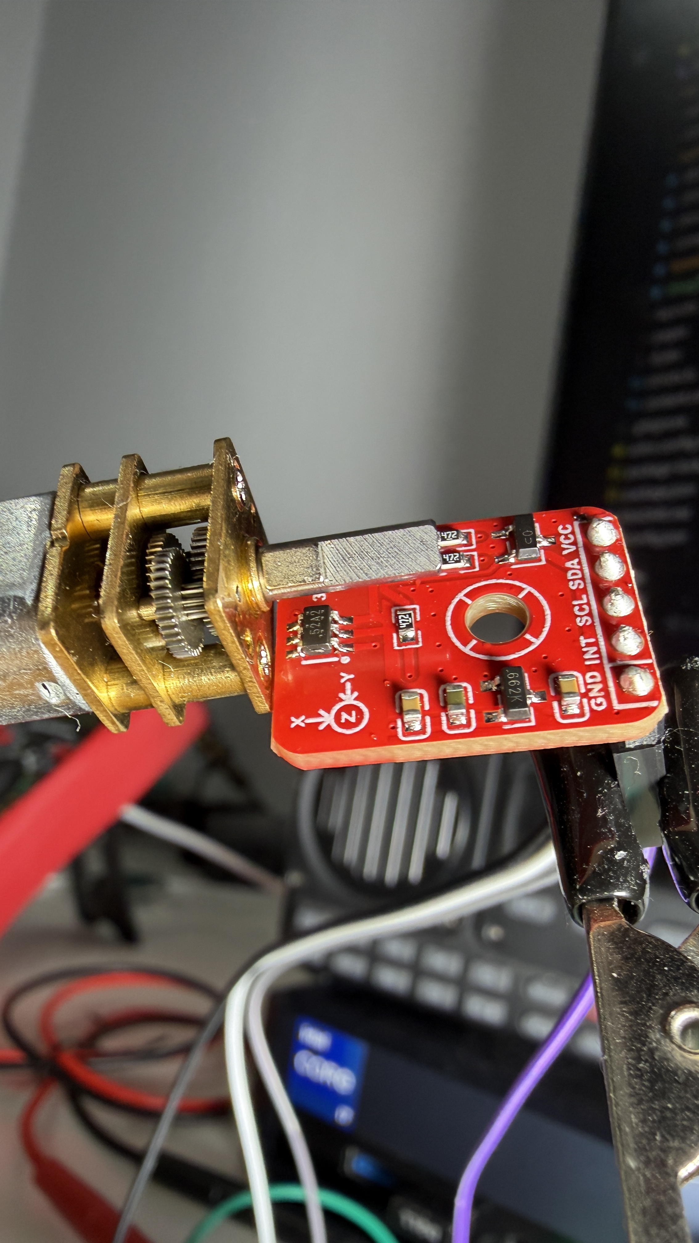
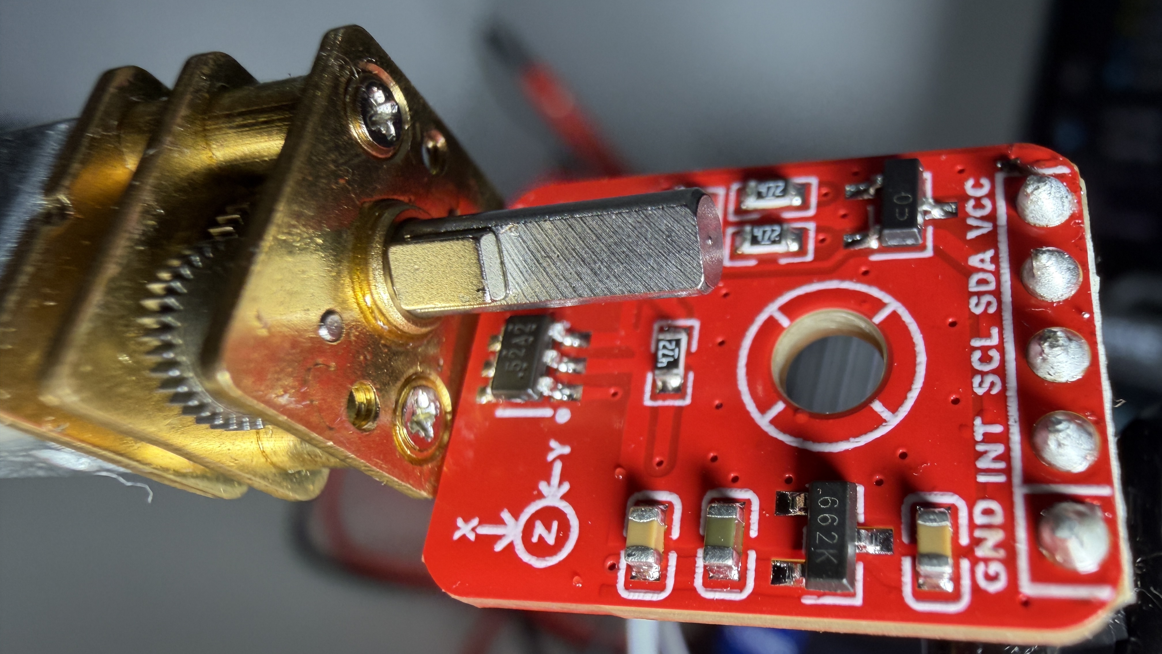
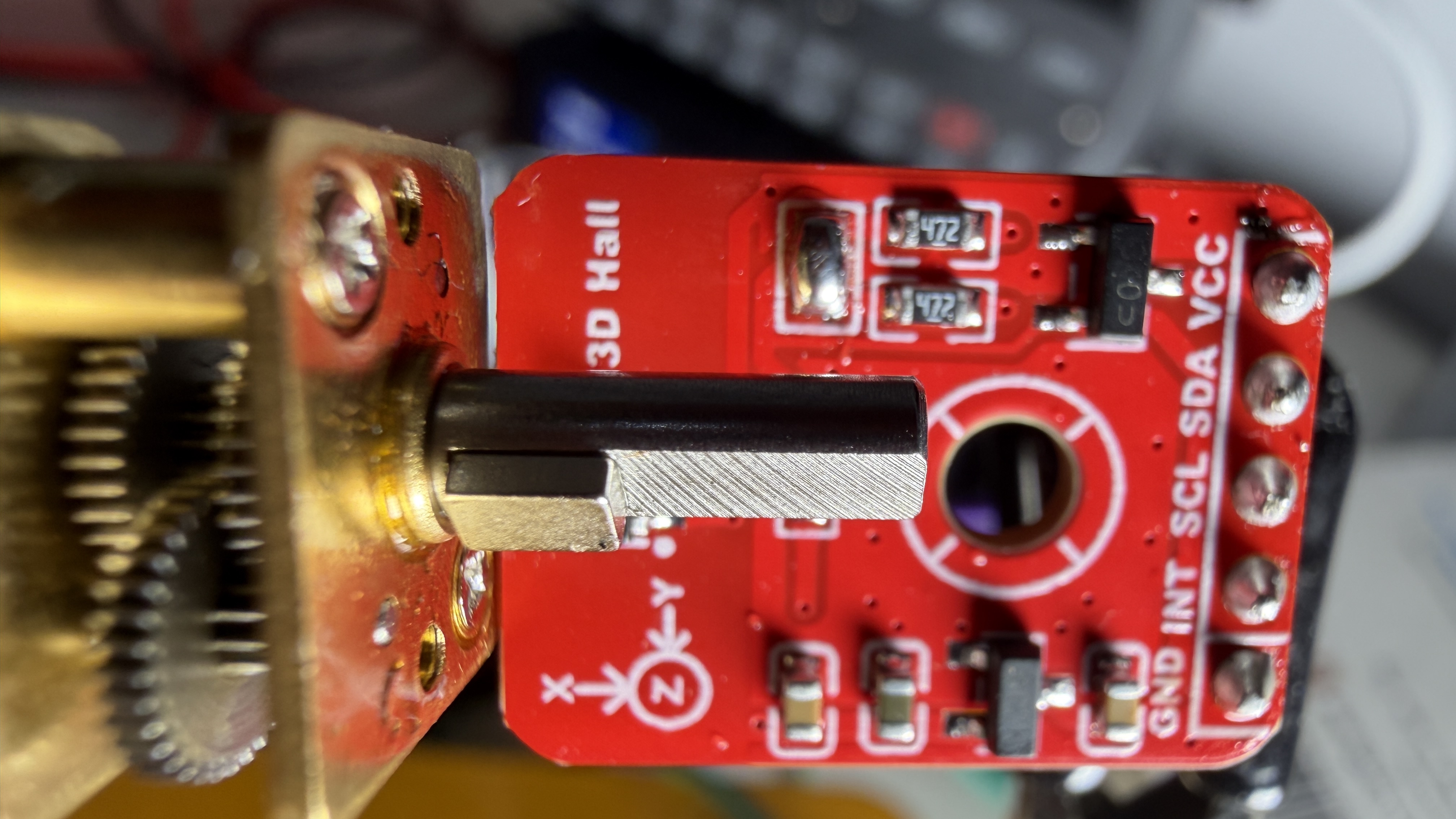
For the last few weeks I have been chasing one very simple thing: I want to know exactly how far each of Ariwoo’s wheels has turned, and how fast. On a self-balancing robot that one number is everything. If the wheel position is noisy, the balance loop ends up fighting ghosts - it tries to correct for wobble that isn’t really there. So a clean, trustworthy angle is not just a nice-to-have. It is the foundation.
How I ended up here
I did not land on the TMAG5273 on day one.
I started with the AS5600 - cheap, everywhere, does the job. But it has a fixed I2C address, which means you cannot put two of them on the same bus. Ariwoo has two wheels. most importantly, the magnetic orientation I have is a big problem, as the official documentation expects me to use diametric circular magnet, perfectly on the axis od rotation. But, I need it working on radial orientation with rectangular magnet.
Then I moved to the MT6701, which is a lovely 14-bit part. Much better resolution. The angle is computed on the chip. you ask it “what angle?” and it hands you a finished number. I burnt the IC last week accidentally so I am waiting to get few more before deciding how good this sensor is.
Why the TMAG5273 has won me for now:
Most magnetic encoders give you an answer. The TMAG5273 gives you the raw magnetic field. The Bx, By and Bz components straight over I2C and lets you decide what to do with them.
That sounds like more work, and honestly it is. But it means all the correction lives in my firmware, where I can see it and tune it. The angle is just:
angle = atan2(By, Bx)…and because I have the raw axes, I can normalise out the imperfections of my own magnet instead of being stuck with whatever the chip decided. There is even room to bolt on a lookup table later if I want to chase the very last bit of distortion.
It also has four selectable I2C addresses from the factory - which quietly solves my “two wheels, one bus” problem that killed the AS5600. Two encoders, one I2C bus, no collision.
Getting a clean angle out of it
Raw field is great, but raw field is also noisy, and the magnet is never perfectly centred so the circle you’d hope to trace in the Bx–By plane comes out as a slightly squashed ellipse. So I stack three things on top:
-
Auto-calibration.
When a wheel first spins through a full turn, the firmware watches the min and max of Bx and By and learns the offset and amplitude of this specific magnet. Nothing is hard-coded - it calibrates to the hardware it actually has, every boot.
-
A 2-state Kalman filter.
The state is [angle, angular velocity]. Between samples it predicts the angle forward using velocity; when a fresh measurement arrives it corrects. It fuses prediction with measurement, roughly halves the noise versus the raw reading, and - importantly - handles variable timing correctly, because I run it off micros() rather than a fixed loop rate.
-
A hysteresis quantiser.
This snaps the output to clean 0.25degree steps, but only commits a new step once the angle has clearly moved past a 0.5degree dead-band. The effect is that when the wheel is sitting still, the reading sits still too - no jittering back and forth across a boundary - and the output stays monotonic as it turns.
Out of all that I get a smoothed angle, a continuous (never-wrapping) count, and a velocity estimate straight from the Kalman state - which is exactly the [position, velocity] pair I need for the controller.
it is only as good as your magnet.
My current calibration reads X_AMP = 0.645 and Y_AMP = 2.910. That is a 4.5times difference between the two axes. In plain terms: my magnet is not seated straight, so the field is much stronger on one axis than the other and the ellipse is badly squashed.
The Kalman filter is doing heroic work to keep that usable - but it cannot fix physics. No filter can. The real fix is mechanical: the magnet, get it centred at the right gap, and re-run one calibration spin. With the field balanced, this exact same code holds half a degree comfortably, and below a quarter-degree once the magnet is properly close. That is probably the most useful lesson from this whole exercise: a good estimator buys you a lot, but it is never a substitute for getting the hardware and sensor right. Fix the magnet first.
This is the 5th iteration of the code at the time of posting the video. Also, please be informed that I use arduino for rapid prototyping and will be using ESPIDF for firmware development.
#include <Wire.h>
#include "SparkFun_TMAG5273_Arduino_Library.h"

#define I2C_SDA 8
#define I2C_SCL 9
#define I2C_HZ 400000

#define ACCUM_N 6

// Kalman tuning
// Q_ANGLE: trust the sensor more, lower Q, smoother but more lag.
// Q_VEL: how quickly velocity can change (high for aggressive motor control).
// R_MEAS: measurement noise variance.
// Set to (noise_std)^2 from your log.
// Current calibration (X_AMP=0.645): noise_std ~ 1.61 deg, R = 2.59
// Good calibration (X_AMP >= 1.3):   noise_std ~ 0.88 deg, R = 0.77
// Ideal calibration (X_AMP >= 3.0):  noise_std ~ 0.40 deg, R = 0.16
#define Q_ANGLE 0.05f
#define Q_VEL 100.0f
#define R_MEAS 2.59f

// Hysteresis quantiser
// STEP: output resolution (degrees).
// HYST: deadband to cross before advancing to next step.
// Set HYST = STEP * 2 for strict no-backward-step behaviour.
// Set HYST = STEP for normal quantisation.
#define STEP 0.25f
#define HYST 0.50f

// Velocity is measured per full revolution (see below). This is how long we wait
// without completing a turn before we treat the wheel as basically stopped and
// let the speed fall toward zero. Below ~ (360/STALL_S) rpm the reading gets
// rougher; at your ~100 rpm a turn takes ~0.6 s so you're always in the clean path.
#define STALL_S 2.0f

TMAG5273 sensor;

// Auto-calibration (offset + per-axis amplitude for the ellipse)
struct Cal {
  float xMin = 1e9f;
  float xMax = -1e9f;
  float yMin = 1e9f;
  float yMax = -1e9f;
  float xOff = 0, xAmp = 1, yOff = 0, yAmp = 1;
  float calCont = 0, calPrev = -999;

  void update(float x, float y) {
    if (x < xMin)
      xMin = x;
    if (x > xMax)
      xMax = x;
    if (y < yMin)
      yMin = y;
    if (y > yMax)
      yMax = y;
    float xRange = xMax - xMin;
    float yRange = yMax - yMin;
    if (xRange > 0.3f && yRange > 0.3f) {
      xOff = (xMax + xMin) / 2.0f;
      xAmp = xRange / 2.0f;
      yOff = (yMax + yMin) / 2.0f;
      yAmp = yRange / 2.0f;
    }
  }

  // Returns total degrees swept during cal
  float trackCal(float angle) {
    if (calPrev < -900) {
      calPrev = angle;
      return 0;
    }
    float delta = angle - calPrev;
    if (delta > 180)
      delta -= 360;
    if (delta < -180)
      delta += 360;
    calCont += delta;
    calPrev = angle;
    return fabsf(calCont);
  }

  float angle(float x, float y) {
    if (xAmp < 0.05f || yAmp < 0.05f) return 0;
    return fmodf(atan2f((y - yOff) / yAmp, (x - xOff) / xAmp) * RAD_TO_DEG + 360.0f, 360.0f);
  }
} cal;

// Kalman state: [angle, angular velocity].
// P is the covariance. I seed it huge because at power-on I have no idea where
// the shaft is or how fast it's turning, so the filter should lean almost
// entirely on the first handful of measurements until it settles.
float kA = 0; // deg, continuous (never wraps)
float kVel = 0; // velocity (deg/s)
float P[2][2] = { { 5000, 0 }, { 0, 5000 } }; // error covariance. if large, then it means it is uncertain at start

void kalmanPrediction(float dt) {
  // Coast the angle forward on the last known velocity...
  kA += kVel * dt;
  // ...then grow P, since a prediction is always less certain than a real reading.
  // (P = F*P*F' + Q, F = [[1,dt],[0,1]], written out by hand - not worth a matrix lib for 4 elements.)
  float p00 = P[0][0] + dt * (P[1][0] + P[0][1]) + dt * dt * P[1][1] + Q_ANGLE;
  float p01 = P[0][1] + dt * P[1][1];
  float p10 = P[1][0] + dt * P[1][1];
  float p11 = P[1][1] + Q_VEL;
  P[0][0] = p00;
  P[0][1] = p01;
  P[1][0] = p10;
  P[1][1] = p11;
}

void kalmanUpdate(float measAngle) {
  // Gap between the measurement and our prediction. Wrap to +/-180, otherwise a
  // reading of 1 deg against a prediction of 359 deg looks like a 358 deg jump
  // and the estimate lurches at every 0/360 crossing.
  float innov = measAngle - kA;
  while (innov > 180){
    innov -= 360;
  }
  while (innov < -180){
    innov += 360;
  }
  // Gain = how much to trust this reading vs the prediction. A noisy sensor
  // (large R_MEAS) shrinks the gain so we mostly ignore it - that's the one knob.
  float S = P[0][0] + R_MEAS;
  float K0 = P[0][0] / S;
  float K1 = P[1][0] / S;

  // Fold the correction into the state
  kA += K0 * innov;
  kVel += K1 * innov;

  // A measurement just reduced our uncertainty, so pull P back down.
  float p00 = (1 - K0) * P[0][0];
  float p01 = (1 - K0) * P[0][1];
  float p10 = P[1][0] - K1 * P[0][0];
  float p11 = P[1][1] - K1 * P[0][1];
  P[0][0] = p00;
  P[0][1] = p01;
  P[1][0] = p10;
  P[1][1] = p11;
}

// 0.25 degree hysteresis quantiser
float stepOut = 0; // output: last committed quantised angle
bool stepInit = false;

void quantise(float contAngle) {
  if (!stepInit) {
    stepOut = contAngle;
    stepInit = true;
    return;
  }
  float err = contAngle - stepOut;
  if (err >= HYST) {
    stepOut += floorf(err / STEP) * STEP;
  } else if (err <= -HYST) {
    stepOut += ceilf(err / STEP) * STEP;
  }
}


// Warp-immune velocity: time one full revolution
// The off-axis magnet bends the angle so the per-sample speed is useless, but the
// continuous angle still advances exactly 360 deg per REAL turn (the warp is a
// bijection of the circle). So we clock how long each full turn takes and the
// distortion cancels out entirely - no LUT, no magnet fix, any cal.
// velRev is SIGNED: + and - encode direction.
// Trade-off: it updates once per turn and reports the trailing-turn average.
// You cannot get clean SUB-revolution velocity from a warped angle - that
// information isn't in the signal. For balancing, the IMU is your fast loop;
// this is the wheel-speed/odometry term, which tolerates the lag.
float revAng = 0;
uint32_t revUs = 0;
bool revInit = false;
float velRev = 0; // deg/s
float xAccumulator = 0;
float yAccumulator = 0;
int accumN = 0;
bool calDone = false;
uint32_t prevUs = 0;
void setup() {
  Serial.begin(115200);
  while (!Serial) delay(10);

  Wire.begin(I2C_SDA, I2C_SCL, I2C_HZ);
  delay(20);

  uint8_t addr = TMAG5273_I2C_ADDRESS_INITIAL;
  if (sensor.begin(addr, Wire) != 1) {
    addr = 0x35; // last resort...
    if (sensor.begin(addr, Wire) != 1) {
      Serial.println("FATAL");
      while (1); //noooooo :-/
    }
  }
  Serial.printf("TMAG5273 at 0x%02X\n", addr);
  sensor.setMagneticChannel(TMAG5273_X_Y_Z_ENABLE);
  sensor.setTemperatureEn(false);
  sensor.setAngleEn(TMAG5273_NO_ANGLE_CALCULATION);
  sensor.setOperatingMode(TMAG5273_CONTINUOUS_MEASURE_MODE);
  prevUs = micros();
}

void loop() {
  if (sensor.getMagneticChannel() == 0) {
    delay(5);
    return;
  }

  float rx = sensor.getXData();
  float ry = sensor.getYData();
  cal.update(rx, ry);

  xAccumulator += rx;
  yAccumulator += ry;
  accumN++;
  if (accumN < ACCUM_N) return;

  float ax = xAccumulator / ACCUM_N, ay = yAccumulator / ACCUM_N;
  xAccumulator = 0;
  yAccumulator = 0;
  accumN = 0;

  uint32_t now = micros();
  float dt = (now - prevUs) * 1e-6f;
  if (dt < 0.0001f || dt > 1.0f) dt = 1.0f / 49.0f; // clamp
  prevUs = now;

  float rawAng = cal.angle(ax, ay);

  // Cal phase
  if (!calDone) {
    float swept = cal.trackCal(rawAng);
    // Require >380degree AND both amplitudes settled. Y will grow here.
    if (swept > 380.0f && cal.xAmp > 0.3f && cal.yAmp > 0.5f) {
      calDone = true;
      // Initialise Kalman with first real measurement
      kA = rawAng;
      kVel = 0;
      stepOut = 0;
      stepInit = false;
      Serial.printf("CAL LOCKED: X_OFF=%.3f X_AMP=%.3f Y_OFF=%.3f Y_AMP=%.3f\n", cal.xOff, cal.xAmp, cal.yOff, cal.yAmp);
    } else {
      Serial.printf("[CAL %.0fdeg] ang=%.1fdeg X_AMP=%.3f Y_AMP=%.3f\n", swept, rawAng, cal.xAmp, cal.yAmp);
    }
    return;
  }

  // Smooth position (warped, but continuous and correct on average)
  kalmanPrediction(dt);
  kalmanUpdate(rawAng);

  // kA is already continuous (the filter runs on the unwrapped angle, so it
  // accumulates and never jumps). Make a SEPARATE wrapped copy for the 0-360
  // display - different name so it can't shadow the global kA.
  float kDisp = fmodf(kA + 36000.0f, 360.0f);

  // Quantise the CONTINUOUS angle, not the wrapped one - otherwise it sees a
  // -360 cliff every revolution.
  quantise(kA);

  //per-revolution velocity (the trustworthy number)
  if (!revInit) { revAng = kA; revUs = now; revInit = true; }
  float dPos = kA - revAng;
  float held = (now - revUs) * 1e-6f;
  if (fabsf(dPos) >= 360.0f) { // a full turn completed (either direction)
    if (held > 1e-4f) velRev = dPos / held;
    revAng = kA; revUs = now;
  } else if (held > STALL_S) { // no full turn for a while, nearly stopped
    velRev = dPos / held; // small partial speed, tends to close to 0
    revAng = kA; revUs = now;
  }
  float rpm = velRev / 6.0f;

  Serial.printf(
    "t=%8lu raw=%6.1fdeg kalman=%6.1fdeg step=%7.2fdeg | cont=%8.1fdeg (%5.2f t) | inst=%7.1f | vel=%7.1fdeg/s rpm=%6.1f\n",
    (unsigned long)millis(),
    rawAng,
    kDisp,
    fmodf(stepOut + 36000.0f, 360.0f),
    kA, kA / 360.0f,
    kVel,        // instantaneous Kalman velocity - warped, reference only
    velRev,      // per-rev velocity - the real one
    rpm);
}
logs: